IEC60598 Clause 11.2 Electrical Appliance Tester Clearances Creepage Distances And Solid Insulation
IEC60598 Clause 11.2 Electrical Appliance Tester Clearances Creepage Distances And Solid Insulation
- Model:
IEC60598 Clause 11.2 Electrical Appliance Tester Clearances Creepage Distances And Solid Insulation
IEC60598 Clause 11.2 Electrical Appliance Tester Clearances Creepage Distances And Solid Insulation
Product information:
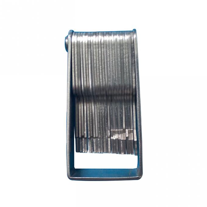
The test gauges is conforms to IEC60884-1, IEC60598,IEC60335 etc., it is used to determine the shortest path between two conductive parts, or between a conductive part and the bounding surface of the equipment, measured along the surface of the insulation, with specifications made according to the requirements.
The creepage distances gauges is with 23 creepage distance gauges:
1.0mm/1.2mm/1.4mm/1.5mm/1.6mm/2.0mm/2.4mm/2.5mm/2.8mm/3.0mm/3.2mm/3.3mm/3.5mm/4.0mm/4.5mm/5.0mm/5.5mm/6.0mm/6.3mm/6.4mm/6.5mm/7.0mm/8.0mm
Material: Stainless steel
Parts detailed in the table of Annex M shall be adequately spaced. Creepage distances and clearances shall be not less than the values given in Tables 11.1 and 11.2.
Values for creepage distances and clearances may be found for intermediate values of working voltages by linear interpolation between tabulated values. No values are specified for working voltages below 25 V as the test voltage of Table 10.2 is considered sufficient.
Distances between current-carrying parts of opposite polarity shall comply with the
requirements for basic insulation.
11.2.1 Compliance is checked by measurements made with and without conductors of the largest section connected to the terminals of the luminaires.
The contribution to the creepage distance of any groove less than 1 mm wide is limited to its width.
Any air gap less than 1 mm wide is ignored in calculating the total clearance, unless the total clearance is less than 3 mm where one third of the air gap width shall be taken into account.
For luminaires provided with an appliance inlet, the measurements are made with an appropriate connector inserted.
Distances through slots or openings in external parts of insulating material are measured with metal foil in contact with the accessible surface. The foil is pushed into corners and similar places by means of the standard test finger specified in IEC 60529, but it is not pressed into openings.
Internal creepage distances in permanently sealed components are not measured. Examples of permanently sealed components are components sealed-off or compound filled.
The values in Table 11.1 do not apply to components for which separate IEC publications exist, but do apply to mounting and accessibility distances to the component when it is incorporated in the luminaire.
Creepage distances at a supply terminal shall be measured from the live part in the terminal to any accessible metal parts, and the clearance shall be measured between incoming supply wiring and accessible metal parts, i.e. from a bare conductor of the largest section to the metal parts which can be accessible. At the internal wiring side of the terminal, the clearance shall be measured between live parts of the terminal and accessible metal parts (see Figure 24).
NOTE The measurements of the clearances from supply and from internal wiring differ because the luminaire manufacturer does not have control over the length of insulation removed from the supply wiring by the installer.
When creepage distances and clearances are determined at bushings, cord anchorages, wire carriers or clips, the measurement shall be made with the cable fitted.