


Electrical IEC Testing Equipment Impact Durability For Hammer IEC6074-2-6
Electrical IEC Testing Equipment Impact Durability For Hammer IEC6074-2-6
- Model:
Electrical IEC Testing Equipment Impact Durability For Hammer IEC6074-2-6
Electrical IEC Testing Equipment Impact Durability For Hammer IEC6074-2-6
Product information:
Impact durability test system for hammer is suitable for the durability test of the electric tool under 3KW. This tester meets the requirement of IEC6074-2-6:2003 standard. It is the ideal test equipment for professional testing organizations and electric tools manufacturers.
The electric hammer no-load life test and durability test bench is according to the standard requirement IEC6074-2-6, Figure 103, loading electric hammer or electric drill, to make it intermittent operation, test electric hammer or electric drill whether it is possible to occur substandard requirements of the electrical and mechanical hazards in normal use.
Test principle and structure:
No-load operation test: Rotary hammers with “drill only mode” are operated at no-load with the impact mechanism disengaged for 12 h at a voltage equal to 1.1 times the rated voltage, and then for 12 h at a voltage equal to 0.9 times rated voltage.
Each cycle of operation comprises an “on” period of 100 s and an “off” period of 20 s, the “off” periods being included in the specified operating time.
During the test, the tool is placed in three different positions, the operating time, at each voltage, being approximately 4 h for each position.
Note; The change of position is made to prevent abnormal accumulation of carbon dust in any particular place. Examples for the three positions are horizontal, vertically up and vertically down.
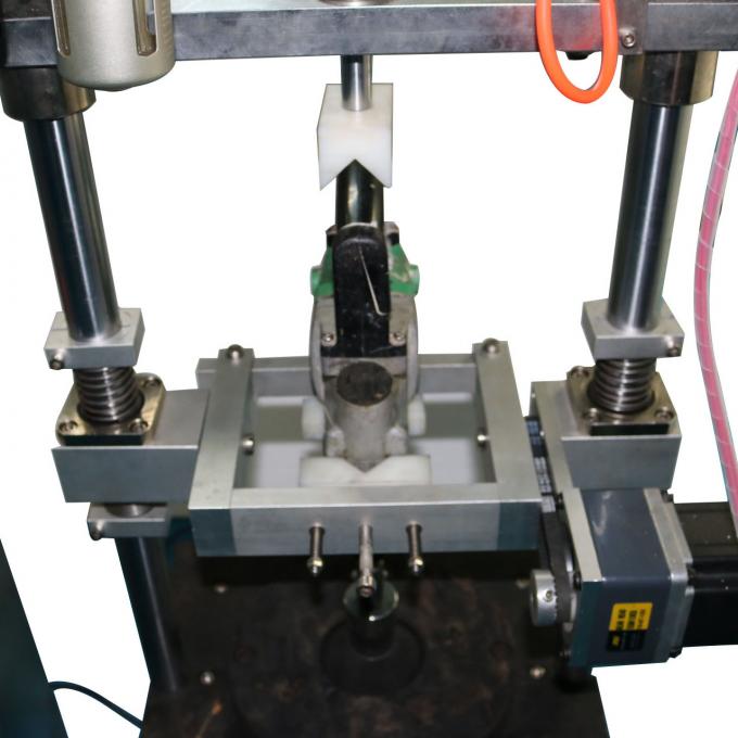
All hammers, including hammers with drill only mode, are mounted vertically in a test apparatus as shown in Figure 103 and are operated at rated voltage or at the mean value of the rated voltage range, for four periods of 6 h each, the interval between these periods being at least 30 min.
During these tests, hammers are operated intermittently, each cycle comprising a period of operation of 30 s and a rest period of 90 s during which the tool remains switched off.
During the tests, an axial force to ensure steady operation of the impact mechanism is applied to the hammer through a resilient medium.
If the temperature rise of any part of the tool exceeds the temperature rise determined during the test of 12.1, forced cooling or rest periods are applied, the rest periods being excluded from the specified operating time.
During these tests, overload protection devices shall not operate.
The tool may be switched on and off by means of a switch other than incorporated in the tool.
During these tests, replacement of the carbon brushes is allowed, and the tool is oiled and greased as in normal use.
If the impact mechanism fails mechanically during the test without causing an accessible part to become live it may be replaced by a new one.
Structure:
This equipment is composed of three parts, the electrical control cabinet, the load box and the mechanical device.
1. Electrical control cabinet includes MITSUBISHI PLC, 7 Inch Touch screen and control panel;
2. Load box includes adjustable voltage 0-250V, with voltage, current display.
3. Mechanical device as shown in Figure 103, includes 90kg, 180kg, 270kg steel base, including the punch, transfer plate and fixture.
Under 700W,90kg base support, with punch,transfer plate, fixture, without include the electric control |
700W-1200W, 180kg base support,with punch,transfer plate, fixture, without include the electric control |
1200-1800W,270kg base support,with punch,transfer plate, fixture, without include the electric control cabinet |
1800-2500W,360kg base support,with punch,transfer plate, fixture, without include the electric control cabinet |
Technical parameters:
Power supply: 120V/60Hz.
Control: MITSUBISHI PLC control, 7 inch color touch screen control.
Test time: Touch screen can be preset.
Test cycle: 0-999999 time can be preset.
Combination mode: Electrical control cabinet + mechanical device.
Mechanical device as shown in Figure 103, containing 90, 180, 270, 360 kg of steel base, including the punch, transfer plate and fixture.
Size: L1000*W800*H1600mm, about 200kg

IEC Test Equipment
IEC Test Equipment
IEC Test Equipment
